In the previous issue we published a selection of MK Beton's built and forthcoming projects. Here we set out fuller detail on one of the company's most important current projects. For years MK Beton has been preparing to equip its factory for a modular housing system made of prefabricated concrete components. The first step was taken in 1988 with a 130 sq. m unit, set up on the permanent exhibition ground (where it still stands), and with a survey of the visitors: the general public, government bodies and private companies. Dr Seyed Shamsoddin Mojabi was then asked to take charge of the design and engineering of the system, a task he has pursued with real enthusiasm. Alongside the design, the making of the moulds and the prototyping of the components have been proceeding, and more than 80% of the moulds and ancillary equipment, along with a number of sample components, have been produced and set up at the MK Beton factory for visitors to inspect. On completing the work in the near future, the company hopes to enter the market with roughly 1,000 sq. m of built area per month. In this issue Dr Mojabi offers a general account of the modular prefabrication system for a lay readership.
Design and Construction of Housing from Prefabricated Concrete Components
Seyed Shamsoddin Mojabi
The industrial production of buildings, and the mass-production of housing, have long been stated goals of those responsible for planning in Iran. The country's immediate need is for about 35 million square metres of new floor-area a year, whereas, by the conventional methods and the financial means of the public and private sectors, only about 17 million square metres a year can be built. In truth, meeting the short- and long-term needs for housing, schools, health, services and industrial buildings, and securing at least a tolerable floor of quality of life, can only be achieved through industrial methods of building production, and above all through prefabrication and the mass-production of housing.
According to official and semi-official statistics, we use 31-34 person-hours of labour per square metre of residential floor area (direct labour on site, excluding the hours devoted to producing materials and equipment), of which less than half is unskilled and the rest is skilled labour. In Europe, by comparison, the equivalent figure for prefabricated industrial production is only 13.8 person-hours, direct and associated labour combined. The comparison makes plain the advantage of industrial, and especially prefabricated, methods for any thoughtful and capable client who cares about the ease and speed of construction, the beauty and durability of the building, its safety, and above all its resistance to earthquake, together with a lower final cost.
The design of a modular structural system for housing built from prefabricated concrete components has been developed to meet the goal of the industrial production of buildings and mass-production of housing. The studies done to determine the architectural base module for the design and construction of prefabricated concrete housing took into account the cultural, climatic and contemporary needs of the population — as well as the physical characteristics of Iranians, the minimum feasible dimensions and the maximum acceptable dimensions for the spaces of daily life. Various small-scale spatial patterns for bedrooms, bathrooms, WCs, dining rooms and living rooms are gathered into a catalogue for the client. By asking a series of questions and examining the culture, the age range of the users, the price of the housing and many other factors, the housing supplier guides the client towards the best choice.
The patterns involved in designing a modular system can be grouped as follows:
- dimensional patterns (small, mid-scale and large, at different levels);
- functional patterns (aimed at optimising the use of the dwelling);
- formal patterns (the geometry of the design, which depends on many subjective and material factors);
- philosophical patterns (taking up such questions as the primacy of function, the primacy of structure and technique, and the preferred hierarchy of space, time and place).
By a rational and careful use of these patterns, many families of open structural systems can be designed, in which architectural modules generate varied dwellings in many forms. In designing open structural systems the aim is the fewest similar modules combined with the widest possibilities of combination and the greatest room to design architectural space. It is worth noting that no open structural system can be designed without first clarifying the concept of “quality” and arriving at a precise, articulated understanding of what it means.
This short piece is not the place for a full discussion of the theoretical, practical and executive principles of a coordinated modular system; what follows is a brief outline of the modular system that has been designed.
The Base Module
Research to determine the numerical small-scale base module arrived at m₀ = 75 mm, and the architectural base module for Iranian housing at M = 900 mm. In a set of tables the multiples of this base module were compared with the dimensions given in the American book Human Dimensions, and the advantage of the 900 mm architectural base module over simple 600, 1,200 and 1,350 mm base modules was demonstrated. The results of the studies have been published in issues 215 and 216 of the Housing and Urban Development Research Centre, under the titles “Modular coordination in the system of building design and construction” and “Dimensions and criteria in design and construction.”
In the system of prefabricated components presented in this article, the numerical base module — the reference grid — is m₀ = 300 mm. The grid is used in most countries and can be read as a multiple of 2 × 3 × 5. The architectural base module — the reference grid for the design of living space — is M = 900 mm. The architectural modules are laid out on optimised catalogues of small, mid-scale and large dimensions. These modules vary for housing in Tehran or elsewhere, from small cottages to large villas. All of them are multiples of the 900 mm base (M = n × m) and have been chosen after a review of the preferred modular number hierarchies in Europe, Japan, Eastern Europe and the ISO. The hierarchy used favours numbers that are multiples of 1, 2 and 3 from the series 1, 2, 3 and 5; numbers that are shared multiples of all four are chosen. In millimetres these are 1,800, 2,700, 3,600, 5,400, 6,300, 7,200 and 9,000.
By exploiting the additive property of the modules, elegant rhythmic combinations can be reached. For the “minimum housing” that the Ministry of Housing and Urban Development is after, architectural modules of 1,800, 2,700 and 3,600 mm can be used; for the parking levels of high-rise buildings, modules of 5,400 and 6,300 mm.
In this system the architectural module and the structural module are in principle identical; the “neutral module” between two adjacent architectural modules is 300 mm. The neutral-module grid — two perpendiculars, right-to-left and top-to-bottom, over the drawing — is where the structural elements of the building sit; those elements never enter the architectural module, which is the realm of space itself.
To gain greater flexibility in architectural composition and to carry different numbers of storeys, three modes of prefabrication are used together:
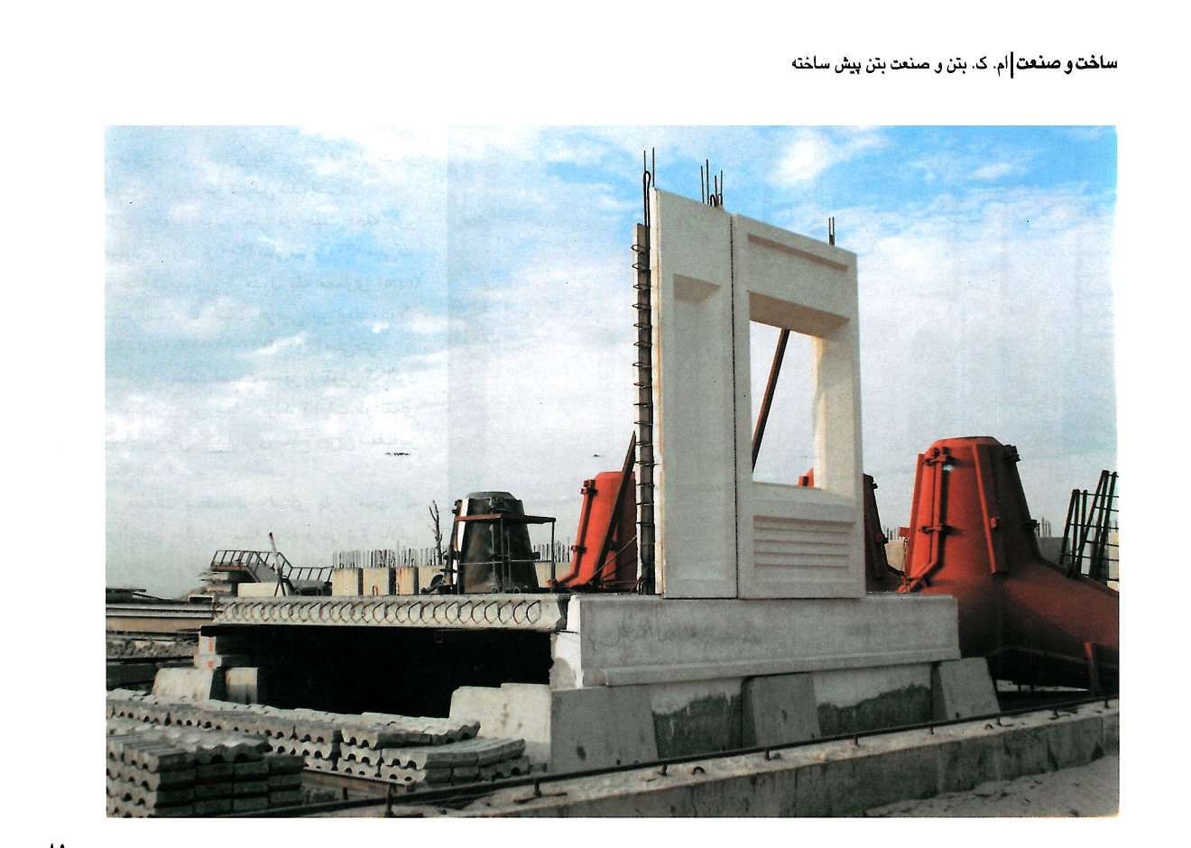
- (a) The largest number of structural superstructure components are hollow-core concrete panels, or lightweight flat concrete panels with specific architectural patterns and shapes.
- (b) A few L-shaped and T-shaped pieces that deliver a wide range of strengths, stabilities, and possibilities of installation and spatial design within the system.
- (c) A number of arch-frame pieces drawing on traditional Iranian architecture, which enrich the range of architectural spaces and give the architect more room to compose and accommodate spaces.
Components of the Structural and Architectural System
1. Foundations have two separate parts with distinct structural roles. First: the footing pieces, divided into four kinds — central, edge, corner and intermediate — which transfer seismic forces to a slender concrete bed of appropriate thickness. Second: the tie beams, prismatic pieces that join the footing pieces into a single system; they are made in cross, T and straight forms.
2. Panels (structural building plates) come in several types and in various modular dimensions: a central load-bearing panel; a lateral load-bearing panel (along an adjoining building); a storey-façade panel; a top-floor terrace-façade panel; and a top-floor façade panel for sloping roofs. Each may have openings for doors, windows or glazing, and each rests on the tie within the footing; on upper floors they sit on horizontal in-situ concrete ties that lock the panels together.
All the regulations and codes on resistance to seismic forces have been observed. The forces involved are vertical and horizontal axial loads, bending moments, and shear between panels at horizontal or vertical levels; the horizontal and vertical ties within the prefabricated pieces take these forces up. The requirements for preventing progressive collapse have also been met, as in current international codes. The steel that resists progressive collapse — binding the pieces vertically from foundation to roof — is made up of hooked steel strands. Shear keys at the face of the horizontal and vertical in-situ ties control the opening of any cracks or the gaps between two adjoining pieces.
All the components are fully consolidated by a series of horizontal and vertical spatial ties, reinforced and poured at roof level between two adjacent pieces after the components of each storey have been installed. All connections between pieces are of the “wet” type; there are no dry, bolted or welded joints in this system.
A prismatic cover piece, about 200 mm wide and of storey height, dresses the neutral module on façade and interior. The neutral module can also be kept invisible on the elevation, but this increases the variety of pieces — by deepening the throat of the vertical ties — and drives cost up. Another prismatic piece serves as a drip on the parapet, into which small, cheap changes allow the architect to reshape the elevation.
3. Floors and ceilings are made from flat hollow-core pieces on the architectural 900 mm base grid along length and width. Along the length — i.e. in the span of the load-bearing direction — modular lengths vary from 2,700 mm to 7,200 mm as multiples of the architectural base module (n × m). Along the width, modular dimensions are 900, 1,800, 2,700 and 3,600 mm. Pieces with various patterns on the soffit, and trapezoidal pieces, are also in view.
Floor pieces are equipped, in the load-bearing direction, with closed steel rings, and are connected at the top of the storey's walls to the vertical rings in the walls by a cast-in-situ tie. Once the longitudinal steel is installed, concrete is poured. The tie's shear capacity and the size of the steel give significant bearing-moment capacity. The longitudinal and transverse connections between floor pieces, through steel shear keys, are strong enough for the floor to be treated as a rigid horizontal diaphragm against seismic forces.
Inside the wall and floor pieces a channel is provided for electrical and telephone cabling, to be covered by aluminium, plastic or wood-and-plaster strips. Hot and cold liquids can also be run as surface-mounted pipes, easily and economically.
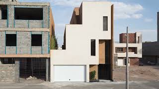
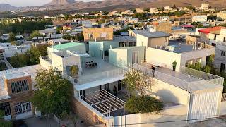
The variety and beauty of the pieces — which allow a client or a complex designer, once aware of the system's wide possibilities, to realise their own architectural ideas — compensate for the difficulty of making moulds and producing the pieces. A final note: using a modular prefabricated system means designing the project with the principles of modular coordination both as tool and as thought. The drawings of a sample villa now under construction in the north of Iran, together with images of the system's pieces, are shown on these pages.